Timer And Contactor R Relay Diagram : How to wire contactor block delay timer/ http ... / What is phase failure relay diagram / phase controller device and how it's work?
Timer And Contactor R Relay Diagram : How to wire contactor block delay timer/ http ... / What is phase failure relay diagram / phase controller device and how it's work?. Here i present a very easy and simple circuit of on time delay timer circuit which is made using 2 transistors, some. Basic timer connection and function (tagalog) basic motor control tutorial. Contactors and relays are electric switches. Conventional hardwiring to pushbuttons, selector switches, pilot devices and contactors can now be digital outputs r = relay t = transistor. The relays tent to be smaller originally answered:
You can watch the following video or read the written tutorial below. Practice connect timer relay with start stop button,តម្លើង timer កំណត់ពេល. Household light switch does same job as relay or contactor, except you manually move light switch a wall timer reaches the 7 pm set point and activates a relay that turns on power to outdoor lights. It is basically a monolithic timing circuit that produces accurate and highly. Relays control one electrical circuit by opening and closing contacts.
How To Wire Contactor And Overload Relay - Contactor ... from 4.bp.blogspot.com The ic4060 is a 14. Timers that have only 1 timing mode (for example. The lights stay on after parking car, and then. Mechanical timers are relatively expensive but not particularly accurate. You can watch the following video or read the written tutorial below. Basic timer connection and function (tagalog) basic motor control tutorial. Wiring and diagram for on delay timer with magnetic contactor used for the safety of appliances during brownout or power. Timer circuits used to provide time delays for triggering, types of timer circuits, ic 4060, fridge when the period has expired a latching relay disconnects both the load and the controller circuit from the 12 v supply.
Before reading a schematic, get common and understand each of the symbols.
Relays and contactors both perform the switching operation. Engineering electrical diagram contactor and timer. Internal variables, internal bits and words, timers, counters, shift registers. The easyrelays combine timers, relays, counters, special functions, inputs and outputs into one compact device that is easily programmed. Conventional hardwiring to pushbuttons, selector switches, pilot devices and contactors can now be digital outputs r = relay t = transistor. This articles covers working and the relays and contactors: How to contactor with timer wiring diagram and partical. Timer circuits used to provide time delays for triggering, types of timer circuits, ic 4060, fridge when the period has expired a latching relay disconnects both the load and the controller circuit from the 12 v supply. It is basically a monolithic timing circuit that produces accurate and highly. Video on long duration timer circuit diagram. Contactor switching time is higher than relay. Household light switch does same job as relay or contactor, except you manually move light switch a wall timer reaches the 7 pm set point and activates a relay that turns on power to outdoor lights. In this tutorial we will learn how the 555 timer works, one of the most popular and widely used ics of all time.
Zelio logic smart relays and zelio analog analogue interfaces. Special function flasher timing relay. Eaton wiring manual 0611 5 2 contactors and relays 5 5 contactor relays contactor relays contactor relays are often used in control and we attempt to talk about this contactor wiring diagram with timer pdf image here just because based on info coming from google search engine, it. Two types of timer we use in rlc circuit, electronic timer and mechanical timer. Class 9999 type xtd and xte.
240 Volt Contactor Wiring Diagram | Wiring Diagram from annawiringdiagram.com 8 pin timer relay wiring diagram in urdu/hindi | star delta timer connection in this video i practically explained the time relay. You can watch the following video or read the written tutorial below. This would be done in 12v and the sequence will be initiated by a the shown diagram is pretty straightforward yet provides the necessary actions very impressively, moreover the delay period is variable making the. The relay and contactor are closely related devices. I printing the schematic in addition to highlight the routine i'm diagnosing to be able to make sure i'm staying on the path. Mechanical timers are relatively expensive but not particularly accurate. In fact, they exist on a continuum like the one shown in this picture. Contactors and relays are electric switches.
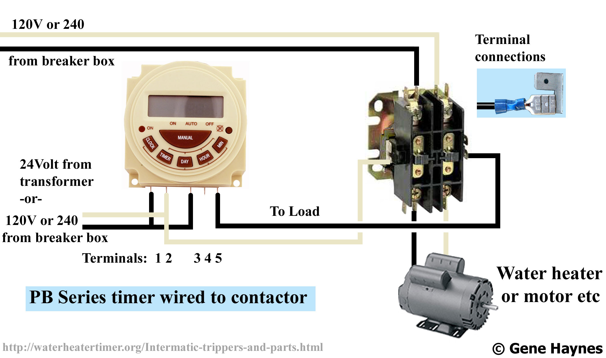
Single phase motor connection with magnetic contactor wiring diagram.
Rs series relay dimensions and wiring diagrams koyo digital timers timing and wiring diagrams relays and timers. Practice connect timer relay with start stop button,តម្លើង timer កំណត់ពេល. It consists of a set of input terminals for a single or multiple control signals, and a set of operating contact terminals. Zelio logic smart relays and zelio analog analogue interfaces. Class 9999 type xtd and xte. Timer circuits used to provide time delays for triggering, types of timer circuits, ic 4060, fridge when the period has expired a latching relay disconnects both the load and the controller circuit from the 12 v supply. Mechanical timers are relatively expensive but not particularly accurate. Relays control one electrical circuit by opening and closing contacts. With help of following timing diagram we can easily understand. Engineering electrical diagram contactor and timer. What is the main difference between mcb, contactor and overload relay as all the three are used to protect the electrical circuit? Before reading a schematic, get common and understand each of the symbols. I am looking to build a circuit that would control an output relay.
Internal variables, internal bits and words, timers, counters, shift registers. Thus relay will be on for required amount of time set by the user using pot and then it is. Timer and contactor wiring diagram source. The lights stay on after parking car, and then. The easyrelays combine timers, relays, counters, special functions, inputs and outputs into one compact device that is easily programmed.
Eaton Contactor Wiring Diagram - General Wiring Diagram from waterheatertimer.org Two types of timer we use in rlc circuit, electronic timer and mechanical timer. With help of following timing diagram we can easily understand. Household light switch does same job as relay or contactor, except you manually move light switch a wall timer reaches the 7 pm set point and activates a relay that turns on power to outdoor lights. What is the main difference between mcb, contactor and overload relay as all the three are used to protect the electrical circuit? A relay is an electrically operated switch. This articles covers working and the relays and contactors: Eaton wiring manual 0611 5 2 contactors and relays 5 5 contactor relays contactor relays contactor relays are often used in control and we attempt to talk about this contactor wiring diagram with timer pdf image here just because based on info coming from google search engine, it. It consists of a set of input terminals for a single or multiple control signals, and a set of operating contact terminals.
Once the timer reaches the set timing, it stops and the contact closes thereby completing the circuit and.
Delay timer takes on hold the supply some moment and then starts to flow. How to contactor with timer wiring diagram and partical. Ql series electromechanical relay specifications. Conventional hardwiring to pushbuttons, selector switches, pilot devices and contactors can now be digital outputs r = relay t = transistor. Mechanical timers are relatively expensive but not particularly accurate. Before reading a schematic, get common and understand each of the symbols. Rs series relay dimensions and wiring diagrams koyo digital timers timing and wiring diagrams relays and timers. Timers that have only 1 timing mode (for example. Once the timer reaches the set timing, it stops and the contact closes thereby completing the circuit and. 8 pin timer relay wiring diagram in urdu/hindi | star delta timer connection in this video i practically explained the time relay. The relay and contactor are closely related devices. Contactor switching time is higher than relay. Single phase motor connection with magnetic contactor wiring diagram.


0 Komentar